RF Signal Analysis
This page will be to cover some basic blind RF signal analysis.
About
Many IoT devices use < 1Ghz signaling for various functions (various sensors, remote controls, device to device communication) with an undocumented and sometimes proprietary protocol. It can often be difficult to understand these without documentation and the aim here is to provide some of the first steps needed to identify and decode some of the data. The hardware used in this demo will be:
A HackRF from Great Scott Gadgets. (https://greatscottgadgets.com/hackrf/)
An RTL-SDR dongle from the rtl-sdr blog that is for sale on amazon. (http://www.rtl-sdr.com/buy-rtl-sdr-dvb-t-dongles/)
Another device from Great Scott Gadgets, the YARD Stick One. (https://greatscottgadgets.com/yardstickone/)
Where to look
One great place to start is with the FCC documentation for the transmitting device, if the device has an fccid then it will have information on file. Some good reference links are below.
Awesome US spectrum allocation graphic: https://upload.wikimedia.org/wikipedia/commons/d/df/United_States_Frequency_Allocations_Chart_2011_-_The_Radio_Spectrum.pdf
Wikipedia page on ISM bands: https://en.wikipedia.org/wiki/ISM_band
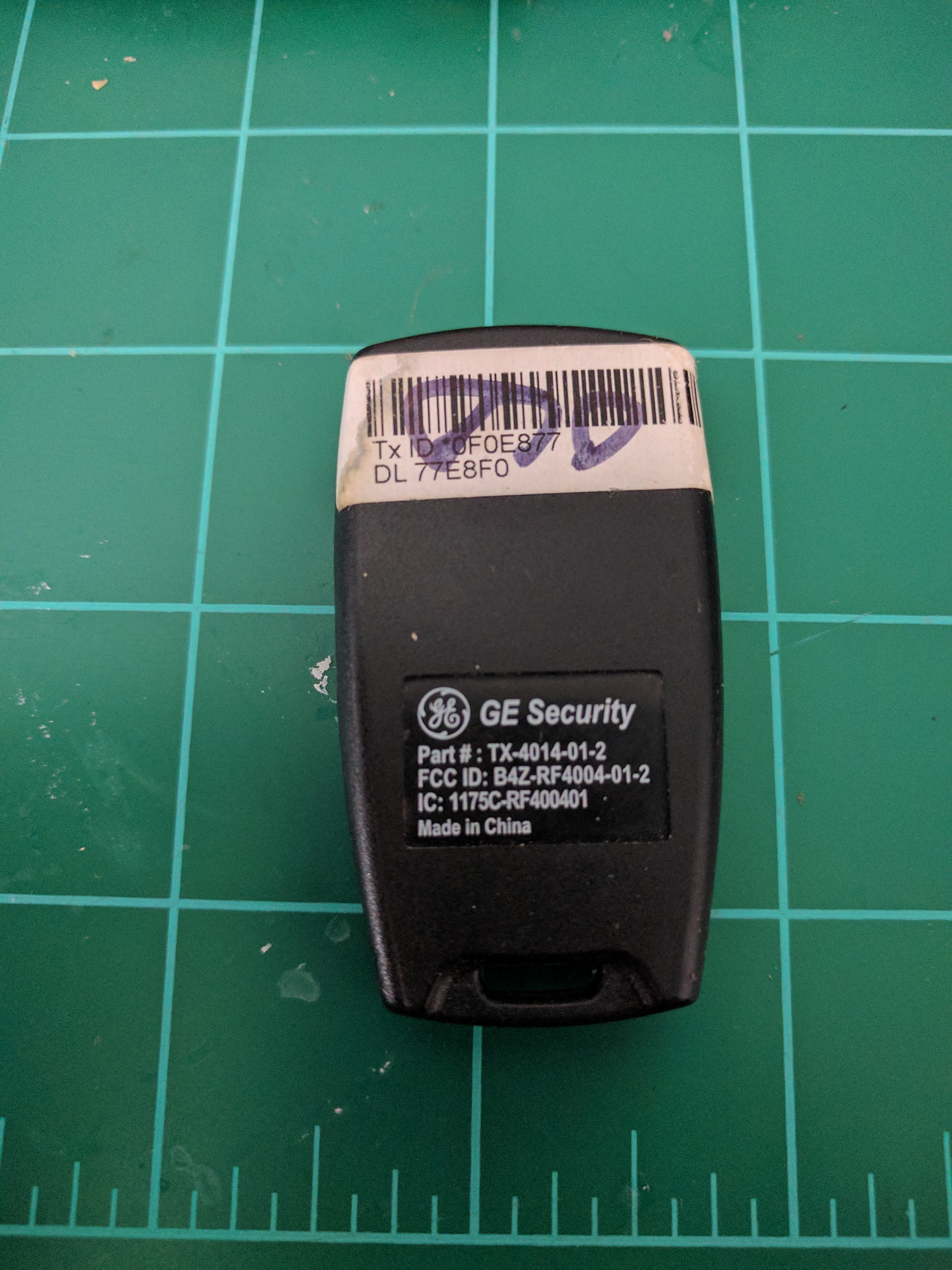
Our demo device right now will be an alarm remote control with the fccid "B4Z-RF400401" that does not have the frequency listed on the package.
We can throw this ID into the https://fccid.io/ site to get some details.
https://fccid.io/B4Z-RF4004-01-2
Now we know where this device is supposed to be transmitting and we can move on to the next steps.
How to look
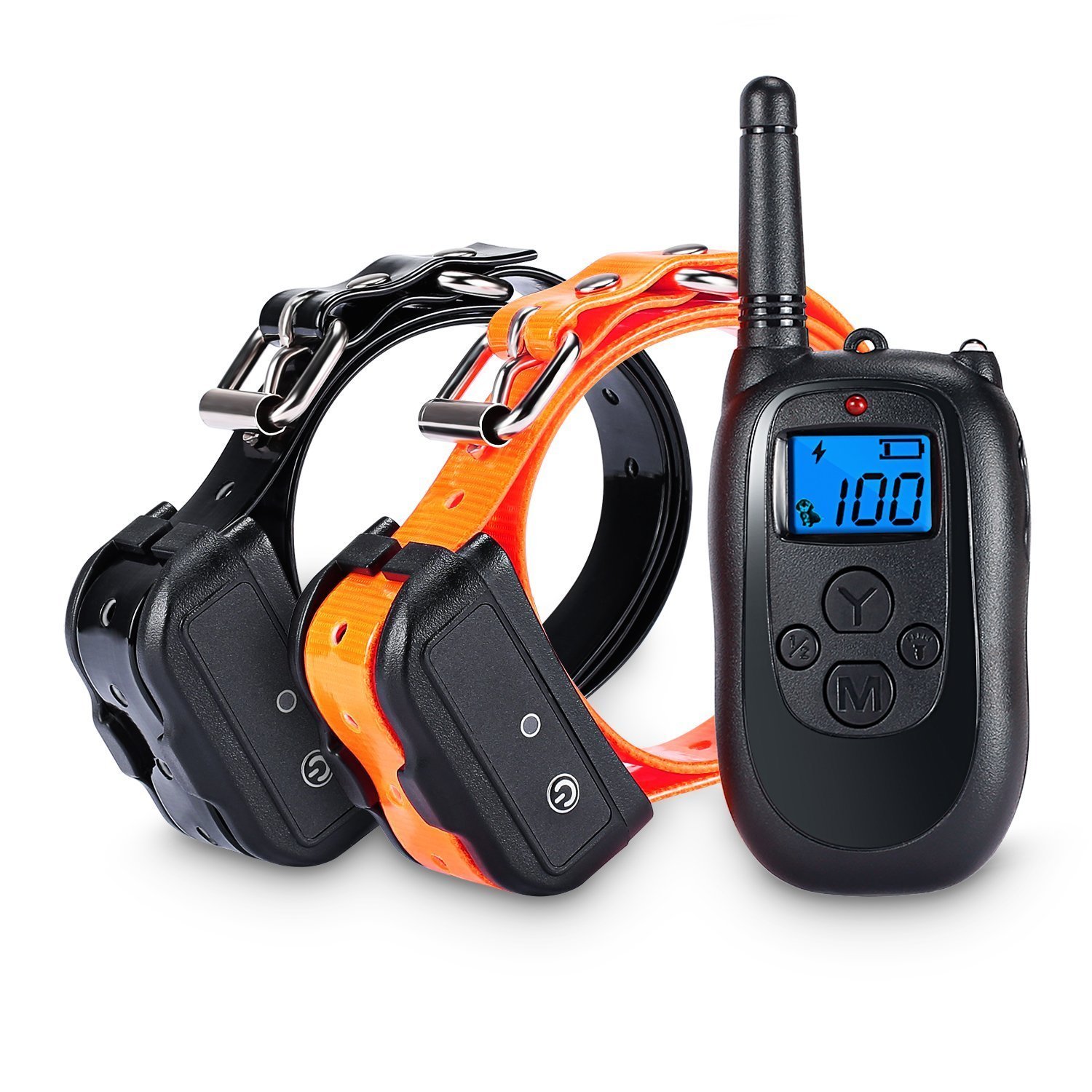
Some favorites are gqrx (linux and mac http://gqrx.dk/) or sdr# (windows http://airspy.com/download/ ) in a higher sample rate mode to inspect the entire band the device operates on to look for the signal. For the rest of the demo I will be using another device with no FCC id. It advertises that it operates at 433mhz. I will be capturing with the RTL-SDR dongle.
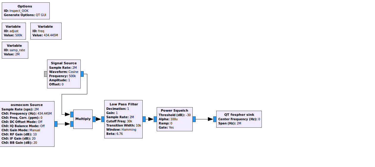
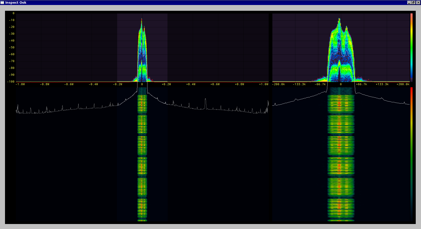
I know where to look for the signal now but the wave form isn't showing me very much. Listening to the demodulated audio does tell me something however, this sounds like Amplitude Shift Keying (ASK) also known as On Off Keying (OOK). Lets verify this with gnuradio and gr-fosphor over the hackrf for a bit higher quality signal.
This absolutely looks like OOK.
Useful link to the Signal Identification Guide wiki: http://www.sigidwiki.com/wiki/Signal_Identification_Guide
Decoding
Our next task will be to determine the data rate, a favorite tool is Inspectrum (https://github.com/miek/inspectrum).
We can see the definite bits here and get a general idea about the baud rate, it looks like it is above 3500 baud but we can refine this! Another useful tool is Universal Radio Hacker (https://github.com/sthysel/urh) that can take a bunch of the work out of demodulating and decoding a signal.
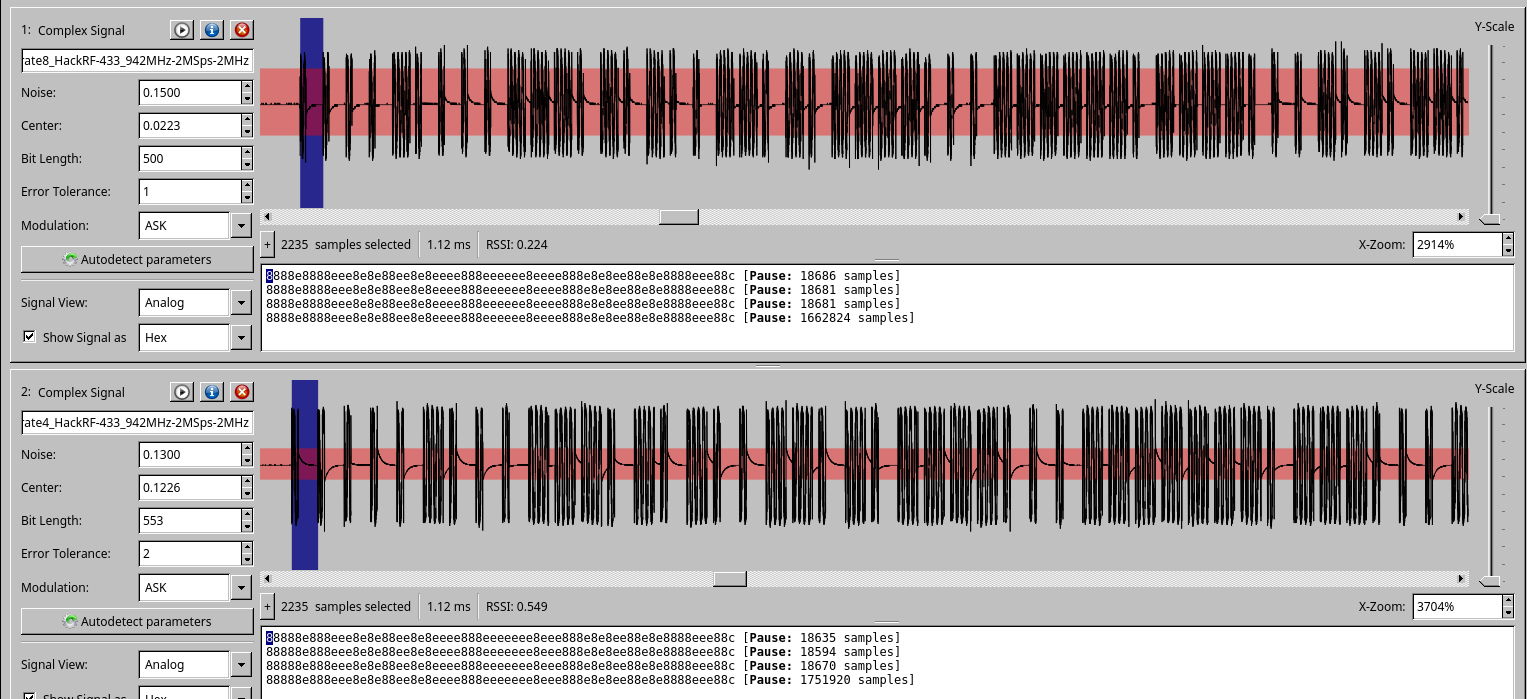
Knowing the approximate baud rate and our sample rate of 2 million samples per second we can start to fiddle with the bit length and noise level to decode the packets. Things start to settle out at 500 samples per bit. This would give us a baud rate of 4000, this isn't accurate because of the rest of the tinkering but it will let us decode the signal. More careful adjustment will get us closer to the actual rate of 555 samples per second or 3600 baud. At this point we can retransmit these bits with the hackrf and trigger the device but it doesn't give us a clear of an idea what is actually going on.
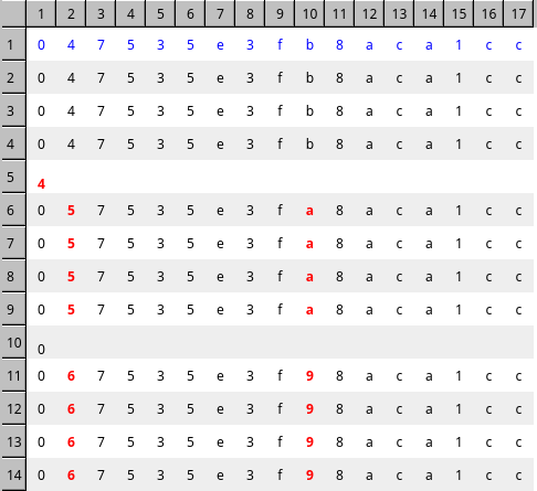
The pattern of bits look like there is some error correction built in, a sequence of 1000 seems to equal 0 and 1110 equals a 1. URH will let us decode this further as seen below.
The resulting packets now look like this.
If we ignore the noise on 5 and 10 we can see a sequence forming. This sequence is the result of changing the power level setting on the remote control. With more changes and monitoring the entire protocol can be decoded.
Sending our own data
With this data we can now use a tool like the YARD Stick One to transmit our own packets to the device. I have posted the complete the code here. https://github.com/rjmendez/ShockCollar
