Interfacing with e-MMC Storage Devices
"Although the information we release has been verified and shown to work to the best our knowledge, we cant be held accountable for bricked devices or roots gone wrong." This page is dedicated to Interfacing with e-MMC Storage Devices. Most of the information is semi-generic and material should be confirmed with your particular setup by referencing the datasheet of your e-MMC device.
e-MMC
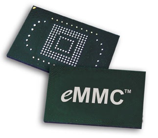
e-MMC is a type of flash storage like MMC but mostly found in embedded devices. e-MMC is similar to NAND but contains an integrated controller which handles Bad Block Management, ECC, and Wear Leveling. It's use allows for the embedded device to offload all the above functionality to integrated hardware. e-MMC access can provide multiple modes of transfer including SD and SPI.
e-MMC devices also sometimes provides a feature known as "1-bit mode", this allows for the transfer of information utilizing only 1 data pin. This mode provides a slower transfer speed than utilizing other modes which require more data pins but allows for easier debugging. Therefore communicating with an eMMC device can be done with as little as 6 wires.
More information on e-MMC can be found on wikipedia at: MMC
Interfacing With An e-MMC Storage Device
Due to it's likeness to MMC and the it's ability to communicate in "SD" mode interfacing with an e-MMC device can be done with as little as 6 wires and an MMC adapter. The required points for any e-MMC setup (Not including data points) are:
- Vcc - IC power-supply pin
- Vccq - Output stage logic power voltage **
- CMD - Command Line
- CLK - Input Clock signal
- GND - Ground Point
** If VccQ is at any other voltage level than 3.3V logic, you will need a logic level conversion circuit to convert the signal for all data lines and clock from your SD reader to that of the e-MMC device.
Data Lines
The number of data lines needed varies depending on the mode you are communicating in. The following are the generally available "modes".
- 8 bits - DAT0 - DAT7
- 4 bits - DAT0 - DAT3
- 1 bits - DAT0
More information on modes can be found in the datasheet for the particular e-MMC device you are working with.
Exploitee.rs e-MMC Adapter
Exploitee.rs member Maximus64 has created a board that is an SDCard breakout which converts the logic level of the CMD and DAT0 lines (for single bit communication mode) to that of the provided voltage level. For ease of use the board contains a jumper to configure a logic level of 1.8 or 2.5 but any voltage between 1.1 and 3.6 can be configured by providing that input to one a pin.
Find out more info on the board at the follow page: Exploitee.rs Low Voltage e-MMC Adapter
Recommended MMC Readers
We've had success with a number of MMC Adapters on the market but the one we have had the best success with is the following: Transcend TS-RDF5K
